Nexus vPC ( Virtual Port Channel)
- Definition: A vPC is a Cisco proprietary technology that allows us to create a virtual link aggregation group (LAG) between two Nexus switches, enabling them to be seen as a single logical entity.
- Enhancing Resilience: The primary purpose of vPC is to enhance redundancy and eliminate the risk of a single point of failure in network designs.
- Loop-Free Topology: By establishing a loop-free topology, vPC facilitates efficient traffic distribution and load balancing across the network.
How to configure vPC -Virtual Port channel in Cisco Nexus switches.
Below are the Basic Steps.
● Enable the vPC feature.
● Create a vPC domain and enter vpc-domain mode.
● Configure the vPC peer keepalive link.
● Configure system priority(Optional)
● Configure vPC role priority(Optional).
● Create the vPC peer link.
● Add Member port to PortChannel and move to vPC.
Quick Configuration Steps for virtual port channel(vPC).
Switch-N9k#Configure terminal
Enable the vPC feature.
Switch-N9k(config)# feature vpc
Switch-N9k (config)# feature lacp
Management IP for keepalive link
Switch-N9k(config)# int mgmt 0
Switch-N9k(config-if)# ip address x.x.x.1
Switch-N9k(config-if)# vrf context management
Create a vPC domain and enter vpc-domain mode.
Switch-N9k (config)# vpc domain #
Switch-N9k (config-vpc-domain)# peer-keepalive destination x.x.x.2
Create the vPC peer link.
Switch-N9k(config)# int ethernet 1/x-y
Switch-N9k(config-if-range)# channel-group # mode active
Switch-N9k(config-if-range)# int po#
Switch-N9k(config-if)# vpc peer-link
Switch-N9k(config-if)# switchport mode trunk
Move the PortChannel to vPC.
Switch-N9k(config)# interface eth 1/2
Switch-N9k(config-if)# channel-group # mode active
!
Switch-N9k(config-if)# interface port-channel #
Switch-N9k(config-if)# switchport
Switch-N9k(config-if)# switchport mode access
Switch-N9k(config-if)# switchport access vlan #
Switch-N9k(config-if)# vpc #


################################################################################
################################################################################


Refer link for vPC understanding from cisco documentation.
Step by step Configuration of Nexus vPC(Virtual Port Channel)
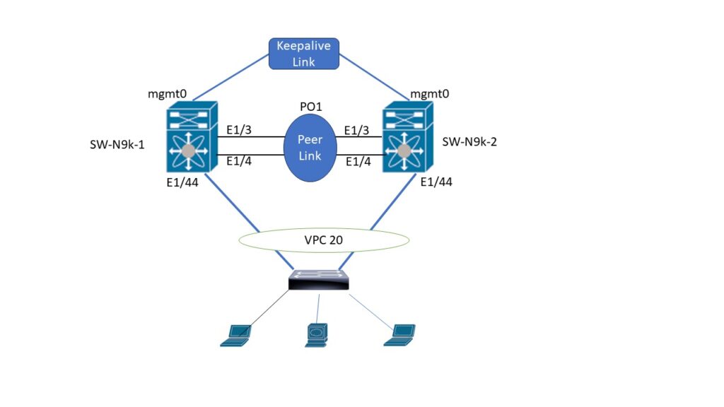
Follow below steps to configure basic setup of vPC.
Step 1. Configure the management interface IP address.
Configure Management port for keepalive link,
Cisco recommend normal ethernet port for keepalive live
SW-N9k-1(config)# int mgmt 0
SW-N9k-1(config-if)# ip address 10.0.0.1
SW-N9k-1(config-if)# vrf context management
SW-N9k-2(config)# int mgmt 0
SW-N9k-2(config-if)# ip address 10.0.0.2
SW-N9k-2(config-if)# vrf context management
Step 2. Enable vPC and LACP.
Enable vpc and port-channel feature before configuring vPC
SW-N9k-1(config)# feature vpc
SW-N9k-1(config)# feature lacp
SW-N9k-2(config)# feature vpc
SW-N9k-2(config)# feature lacp
Step 2a. Create VLAN
SW-N9k-1 & 2(config)#vlan 101
Step 4. Create the vPC domain.
Specify a unique vPC domain ID to distinguish vPC configurations from each other in a multi-vendor environment.
SW-N9k-1(config)# vpc domain 1
SW-N9k-1(config-vpc-domain)# role priority 30 (Optional but reommended)
SW-N9k-2(config)# vpc domain 1
SW-N9k-2(config-vpc-domain)# role priority 20 (Optional but reommended)
Step 5. Configure the peer keepalive link.Destination is Mgmt0 IP of second switch.
keep-alive link monitor the health of vPC peer switches and maintain consistent communication.
SW-N9k-1(config-vpc-domain)# peer-keepalive destination 10.0.0.2
——–:: Management VRF will be used as the default VRF ::——–
SW-N9k-2(config-vpc-domain)# peer-keepalive destination 10.0.0.1
——–:: Management VRF will be used as the default VRF ::——–
Step 6. Configure the vPC peer link. Note that, as for a regular interswitch trunk, trunking must be turned on for the VLANs to which the vPC member port belongs.
A dedicated peer link establish control plane communication between the vPC peer switches. This link is essential for synchronizing state information.
SW-N9k-1(config-vpc-domain)# int ethernet 1/3-4 // Must be 10G port
SW-N9k-1(config-if-range)# channel-group 1 mode active
SW-N9k-1(config-if-range)# int po1
SW-N9k-1(config-if)# vpc peer-link
SW-N9k-1(config-if)# switchport mode trunk
SW-N9k-1(config-if)# switchport trunk allowed vlan 1,101
SW-N9k-2(config-vpc-domain)# int ethernet 1/3-4
SW-N9k-2(config-if-range)# channel-group 1 mode active
SW-N9k-2(config-if-range)# int po1
SW-N9k-2(config-if)# vpc peer-link
SW-N9k-2(config-if)# switchport mode trunk
SW-N9k-2(config-if)# switchport trunk allowed vlan 1,101
Step-7 create the PortChannel for interface eth1/44 and move the PortChannel to the vPC.
Assign the desired physical ports to the vPC domain on each peer switch. These ports will operate as part of the virtual link aggregation group.
Note that the PortChannel number and vPC number can be different, but the vPC number must be the same on both Cisco Nexus Switches
SW-N9k-1(config-if)# int ethernet 1/44
SW-N9k-1(config-if)# channel-group 10 mode active
SW-N9k-1(config-if)# int po10
SW-N9k-1(config-if)# vpc 20
SW-N9k-1(config-if)# switchport access vlan 101
SW-N9k-2(config-if)# int ethernet 1/44
SW-N9k-2(config-if)# channel-group 10 mode active
SW-N9k-2(config-if)# int po10
SW-N9k-2(config-if)# vpc 20
SW-N9k-2(config-if)# switchport access vlan 101